
Cutter Suction Dredger Acceptance Checks Before Overseas Shipment
Overseas shipment is a critical transition point for a cutter suction dredger. A machine that has passed workshop assembly can still arrive with damaged hydraulic lines, contaminated fuel systems, loose electrical terminations, missing lifting documentation, or components that do not match the approved equipment schedule. For quality-control and safety teams, acceptance before dispatch is not simply a factory inspection; it is the final opportunity to verify that the delivered dredger, its loose parts, its records, and its transport arrangement form one controllable package.
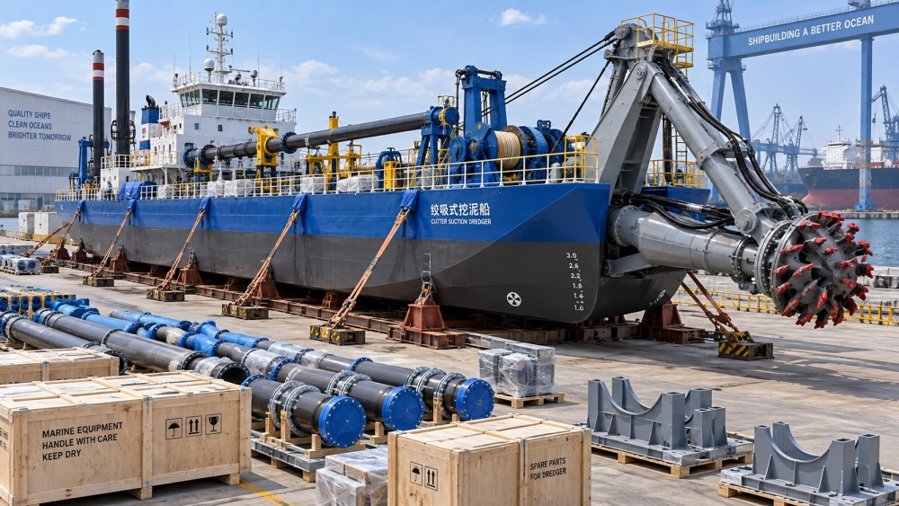
The risk is higher for dredgers than for many standard industrial machines. A cutter suction dredger is commonly supplied as a combination of hull sections, ladder structure, cutter head, dredge pump, diesel engines or electric drives, discharge pipeline components, spuds, winches, anchors, control systems, and auxiliary equipment. Some items travel mounted on the main pontoon, while others are packed separately. If identification, preservation, and shipment interfaces are not checked together, the buyer may face delays during port clearance, assembly, commissioning, or local safety review.
For overseas buyers, the acceptance plan should be agreed before the final inspection date. It should identify the contractual specifications, approved drawings, inspection and test plan, packing list, document register, preservation requirements, and shipment release conditions. The inspection team should also distinguish between defects that prevent shipment and issues that can be documented for correction before commissioning.
Start with configuration control, not appearance
A visually complete dredger is not necessarily a contractually complete dredger. The first acceptance task is to compare the physical equipment against the latest approved technical schedule. This check should cover the dredger type, hull arrangement, pump configuration, drive system, cutter ladder, discharge pipe diameter, electrical supply arrangement, navigation or monitoring equipment, and specified spare parts. Serial numbers should be recorded for major engines, pumps, gearboxes, generators, motors, hydraulic power units, and control cabinets where applicable.
Model naming deserves particular attention when equipment is discussed across quotations, drawings, inspection records, and shipment documents. For example, a buyer reviewing a YLCSD350 cutter suction dredger should ensure that the model designation, project reference, technical specification, and supplied configuration are consistent across all controlled documents. A model reference alone does not confirm installed power, dredging depth, pipeline size, or output capability; those details must be verified against the agreed supply scope.
Quality personnel should request a deviation register before the final inspection. Any substitution of engine brand, cable type, instrument, coating system, valve, hose, or welding consumable may affect maintenance planning, import documentation, local approvals, or future spare-parts availability. A substitution is not automatically unacceptable, but it should be formally reviewed against the contract, operating environment, and safety implications.
Items that should reconcile across documents and equipment
- Main equipment identification plates and serial numbers.
- Approved general arrangement drawing and machinery layout.
- Bill of materials, packing list, and loose-item inventory.
- Electrical single-line diagram, cable schedule, and control-system drawings.
- Spare-parts list, special tools, consumables, and commissioning accessories.
- Certificates for engines, lifting appliances, pressure components, and electrical equipment where specified.
- Inspection reports, non-conformance records, and agreed corrective actions.
A common weakness is treating separately packed items as secondary. Cutter teeth, adapters, ladder pins, floating hoses, pontoons, pipeline bolts, rubber gaskets, anchor wires, lifting slings, and installation tools can determine whether assembly can begin on arrival. Each crate, bundle, and skid should have durable marks that correspond to the packing list and assembly documentation.
Verify structural integrity and weld quality before preservation hides the evidence
The hull, ladder, spud system, winch foundations, pump supports, and lifting points carry significant cyclic and operational loads. Final paint can conceal surface defects, incomplete weld dressing, sharp edges, or poor access for later inspection. The buyer’s acceptance criteria should identify which welds require visual examination, dimensional verification, non-destructive testing, or review of welding records.
Visual inspection should look for undercut, overlap, visible cracking, incomplete weld termination, excessive spatter near moving components, distortion, and water-trapping details. Inspection should also confirm that drain holes, access covers, handrails, walkways, ladders, and guardrails are fitted where shown on the approved drawings. ISO 5817 provides quality levels for imperfections in fusion-welded joints, but the selected quality level and inspection extent must be defined by the project specification rather than assumed. [Source: ISO 5817:2023, Welding — Fusion-welded joints in steel, nickel, titanium and their alloys — Quality levels for imperfections.]
Where non-destructive testing is required, review the reports rather than relying only on a statement that testing was completed. The report should identify the component, weld location, examination method, date, operator or inspection body, acceptance criteria, and result. If repair welding was performed, the record should show that the repair area was re-examined in accordance with the agreed inspection plan.
Dimensional checks should focus on fit-up points that affect transport and site assembly: ladder alignment, spud travel, pontoon mating faces, pipe flange orientation, mounting bolt holes, winch lead angles, and the clearance of rotating equipment. A small dimensional deviation can become a major site problem when sections are assembled far from the manufacturing yard and suitable machining support is unavailable.
Test machinery under controlled conditions and record the evidence
Factory testing does not duplicate every dredging condition, especially where water access, pipeline length, sediment characteristics, or final electrical supply are unavailable. It can still reveal many defects that are expensive to correct after export. The test scope should be realistic, clearly recorded, and linked to the agreed acceptance procedure.
For diesel-driven systems, the inspection team should observe starting sequence, oil pressure stabilization, cooling-water circulation, exhaust condition, alarms, emergency stop response, and abnormal vibration. Fuel, lubrication, cooling, and hydraulic circuits should be checked for leaks at operating temperature and pressure where practical. The buyer should receive the engine manuals, maintenance schedule, warranty terms, and identification details needed for future support.
For electrical systems, acceptance should include enclosure condition, cable gland sealing, earthing continuity, phase identification, control-circuit labeling, insulation resistance testing where applicable, and functional operation of emergency stops and alarms. IEC 60204-1 sets out general requirements for electrical equipment of machines, including protective bonding, control circuits, emergency stopping, and documentation principles. It should be applied where relevant to the supplied machinery and contractual design basis. [Source: IEC 60204-1:2016, Safety of machinery — Electrical equipment of machines — Part 1: General requirements.]
Hydraulic systems require more than a quick visual leak check. Inspect hose routing near hot surfaces and moving sections, verify hose and fitting identification, confirm protection against abrasion, and check that flexible hoses do not impose side loads on connections. Hydraulic hose failure can cause injection injuries, fire hazards, loss of control, and environmental releases. Guards around rotating couplings, belts, shafts, and exposed drives should be secure and removable only with tools where the machinery risk assessment requires it.
Safety-function checks should be witnessed and recorded. Depending on the supplied configuration, this may include emergency stops, cutter-head stop, winch controls, ladder hoist limits, spud controls, low-pressure alarms, high-temperature alarms, bilge alarms, navigation lights, fire extinguishers, and audible warning devices. ISO 12100 is a useful framework for confirming that hazards have been identified and that safeguarding measures follow a risk-reduction process, although it does not replace project-specific legal or marine requirements. [Source: ISO 12100:2010, Safety of machinery — General principles for design — Risk assessment and risk reduction.]
Assess coating, corrosion protection, and storage condition for the voyage
Export readiness includes the period between factory release and commissioning. A dredger may spend weeks in port storage, on deck, in a hold, or at a destination yard exposed to salt spray, condensation, rain, heat, and ultraviolet radiation. Bare machined surfaces, cylinder rods, flange faces, bearings, electrical connections, and open pipe ends require protection suited to the transport duration and destination climate.
Coating acceptance should address surface preparation records, paint system identification, dry-film-thickness measurements, repaired areas, edge coverage, and curing status. ISO 12944 provides a widely used framework for corrosion protection of steel structures by protective paint systems, including environmental corrosivity categories and durability concepts. It does not establish a universal paint thickness for every dredger; the project coating specification must define the selected system and inspection criteria. [Source: ISO 12944-1:2017, Paints and varnishes — Corrosion protection of steel structures by protective paint systems — Part 1: General introduction.]
Open suction, discharge, cooling, and hydraulic connections should be capped or blanked using methods that prevent debris and moisture ingress. Temporary shipping plugs should be clearly identified so they are not mistakenly left in place during commissioning. Desiccants, vapor-phase corrosion inhibitors, shrink wrapping, and sealed crates may be appropriate for sensitive components, but their use should be documented and their condition checked immediately before loading.
Control lifting, sea fastening, and cargo interfaces
A dredger can be mechanically sound yet unsafe to transport if lifting points, weight information, or sea-fastening arrangements are incomplete. Buyers should request the shipping weight and dimensions for each transport unit, including the main hull, ladder, spuds, pontoons, pipeline sections, winches, crates, and heavy loose equipment. The figures should be traceable to the actual configuration, not copied from an early proposal.
Lifting lugs and padeyes should be marked where possible, and the available lifting documentation should state the intended load and lifting arrangement. If a component must be lifted in a particular orientation, that requirement should appear on the crate or transport frame. Loose equipment should not be secured by improvised chains or wire rope without a reviewed lifting and lashing plan.
The International Maritime Organization’s Code of Safe Practice for Cargo Stowage and Securing addresses the safe stowage and securing of cargoes carried by sea, including the need to account for cargo characteristics and anticipated transport forces. The exact responsibilities between supplier, freight forwarder, carrier, and buyer should be established contractually before loading. [Source: International Maritime Organization, Code of Safe Practice for Cargo Stowage and Securing (CSS Code), 2021 edition.]
For containerized accessories, the CTU Code provides guidance on packing, securing, and distributing cargo in cargo transport units. It is particularly relevant to crates containing cutter tools, valves, hoses, electrical panels, spare parts, and small machinery. [Source: IMO/ILO/UNECE, Code of Practice for Packing of Cargo Transport Units (CTU Code), 2014.]
Release shipment only with a usable documentation package
Documentation gaps often appear after the equipment has departed. The receiving team may then be unable to clear customs, assemble the dredger safely, establish maintenance intervals, or prove that supplied components meet the purchase requirements. The final release file should be reviewed as carefully as the physical machine.
Photographs should document equipment condition before loading, package marks, crate interiors where practical, sealed openings, major serial plates, and the final lashing arrangement. They are not a substitute for inspection records, but they can help determine whether damage occurred before or after handover to the carrier.
The most reliable shipment release is based on traceability: every significant component can be located, every accepted deviation is visible, every safety-critical test has evidence, and every transport unit has a defined protection and securing method. That discipline reduces disputes at destination and gives quality and safety teams a practical basis for deciding whether the dredger is genuinely ready to leave the factory.
Related News
- Cutter Suction Dredger Acceptance Checks Before Overseas ShipmentSep 02, 2026YLCSD350 cutter suction dredger acceptance checks: verify configuration, testing, corrosion protection, sea fastening, and documents before overseas shipment.
- Can pallet racking be retrofitted for AS/RS integration in existing warehouses?Sep 11, 2026How does predictive maintenance reduce conveyor downtime? Discover how it ensures seamless AS/RS retrofit success—boosting uptime, ROI, and warehouse automation reliability.
- YLCSD350 Cutter Suction Dredger Specs That Matter in River and Port JobsAug 21, 2026YLCSD350 cutter suction dredger specs explained for river and port jobs—learn how pump, cutter, draft, wear design, and transport factors affect output, risk, and buying decisions.
- How to Evaluate Gantry Crane Structural Analysis for Load Cases and Deflection LimitsAug 06, 2026Crane structural analysis for gantry crane evaluation: learn how to verify load cases, stress results, and gantry crane deflection limits to compare suppliers, reduce risk, and choose a safer design.